6.1 - Capacitors
Core Info and Definitions
A capacitor is a circuit component that stores charge in a circuit by separating equal and opposite charges onto two electrical conductors (plates) with an insulator in between them.
Capacitance, C, defines the quantity of charge Q which can be stored per unit potential difference across the plates. Measured in farads
Capacitance

... where epsilon 0 is the permittivity of free space, epsilon r is relative permittivity of the material, A is the surface area of a plate, and d is the separation between the plates.
Capacitance of an Isolated Conducting Sphere:

... where R is the radius of the sphere.
Total Circuit Capacitance
In series, capacitance sum is determined in a similar way to how resistance is determined with resistors in parallel:

In parallel, it's the opposite - the capacitances are just added to each other:

Capacitor Energy
Capacitor energy can be given as:

... and you can use Q=CV to substitute values in to determine energy with charge.
(You do not need to know the integral derivation. It is only for explanation.)
The work done in moving a charge Q from one plate to another through a constant potential difference V is:

The reason the two energy equations are different is because V is constant in the latter, but not the former. Capacitance is a constant for each capacitor, however.
A capacitor can leak charge . This is because the insulator between the plates is not perfect, so there is a tiny current that passes through them. This charge leakage is more clearly observable when disconnecting a capacitor from the source of emf.
Charging and Discharging
Where x0 is the initial value of the variable, C is capacitance, R is resistance and t is elapsed time:
| Current |
Charge |
PD |
|
| Charging |
 |
|
|
| Discharging |
|
|
|


(... yes, current has the same equation for charging and discharging.)
The time taken for the charge of the capacitor to fall to 1/e (~37%) of its original charge is known as the time constant.

As more charge is added to a capacitor, it gets harder to add more charge to it. This concept is analogous to pumping a car tyre - it is initially easy to add air to it, but the increase of internal pressure makes adding more harder and harder.
Graphical Methods
Take V in discharging for an example. You can apply the natural logarithm "ln" to both sides to separate variables and obtain a straight line in a graph:

In here, the y-intercept is "ln(V0)" and the gradient is "-1/CR". You can use the gradient to find the capacitance of the circuit, and you can use the y-intercept to find the initial pd of the capacitor by raising e to the power of "ln(V0)".
Spreadsheet Modelling
You can model the discharge of a capacitor using a spreadsheet method without using experimental data. This is known as iterative modelling. You can do this with the following equation:

This gives the decrease of charge, so the output of this should be subtracted from the last value of charge. The table looks like this1:
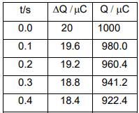
... with a time increment of +0.1.
No comments to display
No comments to display