6.3 - Electromagnetism
Definitions and Core Info
A magnetic field is a field in which a charged particle experiences a force. Its direction is determined by the force experienced by a positive test charge.
Field Lines
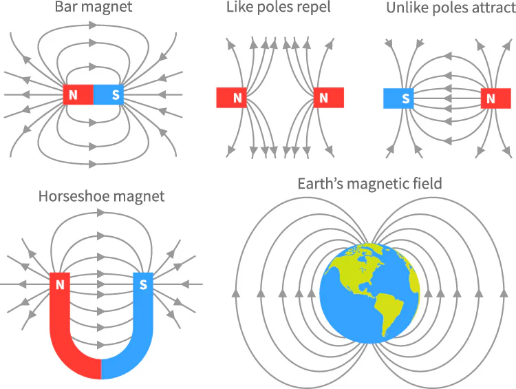
Magnetic Force
Flemings' left hand rule:
- Thumb: Thrust (force)
- Index/First finger: Magnetic field
- Middle/Second: Current
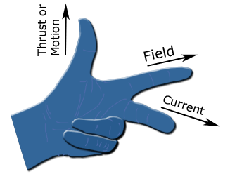
This rule is executed on the right hand (Flemings' right hand rule) if the wire is moving through a uniform magnetic field to determine the force on the wire. Not really necessary once you understand Lenz's law.
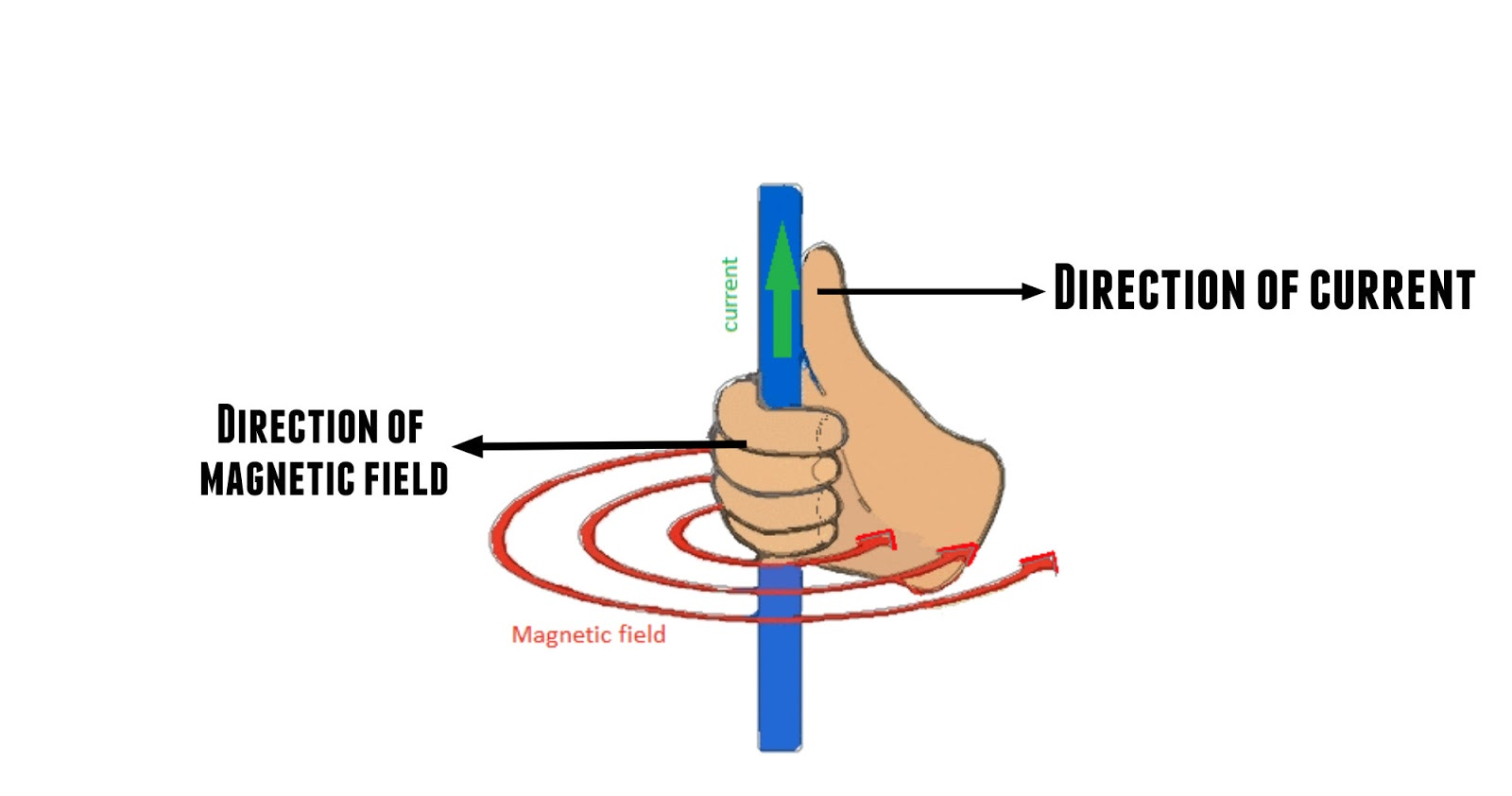
Right hand grip rule:
- Thumb: Direction of magnetic field.
- Grip: Direction of current in the coil.
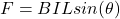
The "thrust" represents the magnetic force on a current-carrying wire/moving charge:
 /
/ 
... where theta is the angle between the wire and the field lines.
In a magetic field, a moving charge moves in circular motion. The radius is derived as:

... where m is the mass of the particle, v is its velocity, B is the magnetic flux density it is going through, and q is its charge.
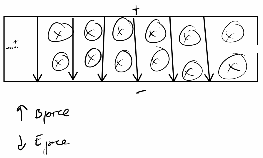
This can be used to perform selection of certain particles by their velocity.
- Particles are charged such that they all have the same charge.
- They are accelerated through an electric field on top of a magnetic field through a vacuum.
- F = BQv, F = Eq, => E = Bv
- Particles with the incorrect velocity will have unbalanced forces, causing them to undergo circular motion upwards or downwards as they pass through the vacuum.
- Particles with the correct velocity will pass through the window.
In a mass spectrometer, charged particles with the selected velocity will pass through the window and undergo circular motion, circling upwards with varying radii depending on mass. Different numbers of these charged particles will interact with different parts of the detector, and their abundances are proportional to generated current due to electron flow.
Electromagnetic Induction
Magnetic Flux

... where B is the magnetic flux density, A is the cross sectional area of the coil, and theta is the angle of the coil from the vertical of the cross section.
Flux linkage:

... where N is the number of turns in the coil.
Faraday's Law
The EMF induced in a coil is equal to the rate of change of magnetic flux linkage.

Lenz's Law
If the magnetic flux linkage through a coil changes, itan willemf induceis induced that drives a current towhose opposemagnetic field opposes the change.change in flux. This opposition occursis duea to the generationconsequence of an equal and opposite magnetic field. This is due to conservation of energy.
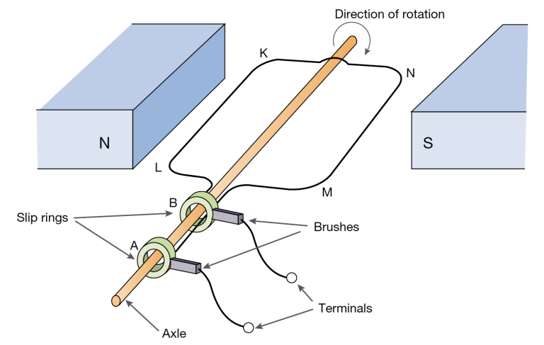
AC Generators
A coil of wire rotates inside a uniform magnetic field. Magnetic flux increases as it reaches 180 degrees, and decreases as it continues turning to 360 degrees. This alternating rate of change of magnetic flux linkage causes an alternating emf to be induced in the coil as per Faraday's law, causing an alternating current to be generated. As the coil rotates, slip rings also rotate with it, which interact with brushes (made from carbon and copper) to allow electrical contact from the slip rings to an external circuit. Contains:
Transformers
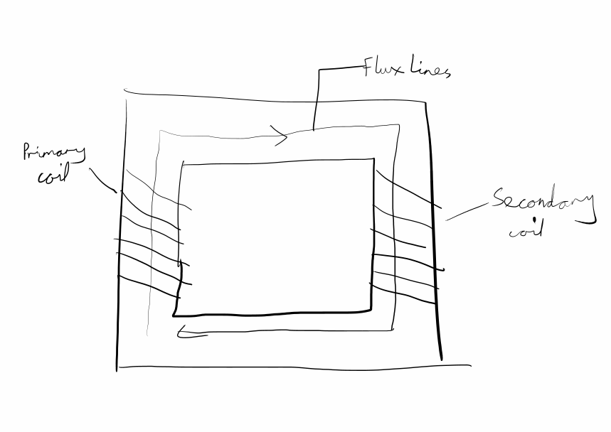
An alternating current is passed through the primary coil, causing an alternating magnetic field to be generated, along with alternating magnetic flux lines through the soft iron core, which maximises retainment of magnetic flux lines due to magnetic shielding. This generates an alternating EMF in the secondary coil due to Faraday's law.

... where Vs and Ns are the EMF and number of turns in the secondary coil, and p is likewise for the primary coil.
Transformers can be >95% efficient, with some reaching over 98.5%99% efficiency.
An Eddy current can be created in the soft iron core due to the magnetic field from the primary coil. This creates an opposing magnetic field and releases energy into the core as heat, reducing efficiency. This is mitigated by laminating the transformer cores - i.e. making them made up of layers of iron stuck together instead of being one solid block of iron.