4.3 - Electrical Circuits
Kirchoff's Laws
- The sum of currents entering a junction in a circuit is equal to the sum of currents exiting this junction. This ensures conservation of charge.
- The sum of emfs in a loop of a circuit is equal to the sum of potential differences of all components in the loop. This ensures conservation of energy.
Resistance Sums
|
Energy must be conserved, so the sum of potential differences of the components must be equal to the pd across all relevant components (which can be emf). As per V = IR, we can express this as:
We can divide both sides by I to get:
|
|
Again, energy must be conserved. Total circuit current can be expressed using Kirchoff's 1st law as:
However, as per Kirchoff's 2nd law, voltage on each branch is equal:
Taking the first equation, as I=V/R:
Dividing through by V gives us:
|


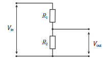
Potential Dividers
Potential difference is split across resistors from the total voltage of a loop in a ratio based on resistance of each component. This enables the delivery of electrical power to multiple parts of a circuit in differing ratios.
Internal resistance
Cells aren't perfect - they still have a small amount of resistance themselves due to differences in the material used for the cells. In manufacturing, this internal resistance is made to be as low as possible, but cannot reach zero.

... where E is emf, I is current, and r is internal resistance. E and r are constant values.
Determining E and r
EMF and internal resistance can be experimentally determined by rearranging the above equation as follows:

Method:
CreatePlaceathepotentialpowerdividersourcesetupin-seriesbattery,withammeter,anfixed resistor,ammeter and a variableresistor.resistor,Connectwith a voltmeter parallel to thefixedpowerresistorsource:
in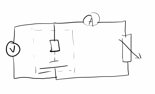
parallel.- Start with a
largehigh value of resistanceon the variable resistorand recordthe ammeter outputcurrent I in ampsandfrom thevoltmeterammeteroutputwith potential difference V in volts from the voltmeter in a table. - Repeat,
reducingdecreasing the resistanceon the variable resistorsuch that the currentincreasesIbydecreasesainproportionalfixedamountintervals as per V=IR. - Plot a graph of V against I and draw a line of best fit. The y-intercept is the
emfemf, and the gradient of the line is the negative oftheinternal resistance.

Multiple Sources of EMF
If two sources of EMF are pointing in opposite directions in a loop, the EMF of the loop is equal to the difference between them. E.g. in the following circuit, the EMF is 9-6=3:
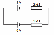
If they were pointing in the same direction, they would add to 9+6=15.