# Module 4

# 4.1 - Charge and Current

## Key info and definitions

## Electric Circuit Components

[![image.png](https://bookstack.asadhussain.net/uploads/images/gallery/2026-02/scaled-1680-/lNSimage.png)](https://bookstack.asadhussain.net/uploads/images/gallery/2026-02/lNSimage.png)

1. **Junction of conductors:** Allows current to split; resistance is typically low but increases with temperature.
2. **Conductors crossing (no connection):** Allows current to flow across a circuit without connecting to the crossing wire; resistance is typically low.
3. **Switch:** Turns current on and off; resistance is low when closed and very high (due to an air gap) when open.
4. **Cell:** Provides a source of energy or e.m.f. (electromotive force); resistance is low or negligible.
5. **Battery:** A combination of two or more cells; internal resistance increases as more cells are added in series.
6. **Terminals:** Provides a connection point for a source of energy; resistance is low.
7. **Lamp:** Transfers electrical energy into light; resistance increases as the current increases.
8. **Fixed resistor:** Controls the amount of current; resistance is fixed and determined by its material (often semiconductors like silicon).
9. **Variable resistor:** Controls current flow manually; resistance changes based on the slider or dial setting.
10. **Fuse:** A safety device that melts if current is too high; resistance is typically low and depends on the wire's dimensions and material.
11. **Heater:** Transfers electrical energy into thermal energy; resistance is typically high.
12. **Ammeter:** Measures the electrical current in a circuit; resistance is very low.
13. **Voltmeter:** Measures the potential difference (e.m.f.) across a component; resistance is very high.
14. **Thermistor:** Responds to environmental temperature; resistance changes in response to the temperature of the surroundings.
15. **Diode:** Restricts current to one direction; resistance is low in forward bias and very high in reverse bias.
16. **Light-emitting diode (LED):** Allows current in one direction and emits light; resistance is low in forward bias and high in reverse bias.
17. **Light-dependent resistor (LDR):** Changes current based on light levels; resistance decreases as light intensity increases.

## Electric Current and Charge

Current is the rate of flow of electrical charge.

[![image.png](https://bookstack.asadhussain.net/uploads/images/gallery/2026-02/scaled-1680-/bJiimage.png)](https://bookstack.asadhussain.net/uploads/images/gallery/2026-02/bJiimage.png)

... where Q is charge and t is time.

Atoms become charged when they gain or lose electrons.

Conventional current travels in the **direction of flow of positive charge** - i.e. the opposite of electron flow.

### Kirchoff's Laws

1. The sum of electrical current into a junction is equal to the sum of electrical current out of a junction. Ensures conservation of charge, as flow of charge into a junction point = flow of charge out of the junction point.
2. In a closed loop of a circuit, the sum of potential differences is equal to the sum of emfs. Ensures conservation of energy, as energy into the circuit = energy out of the circuit.

## Electron Drift Velocity

When conducting electricity, electrons move slowly through the wire at a drift velocity v.

[![image.png](https://bookstack.asadhussain.net/uploads/images/gallery/2026-02/scaled-1680-/V3Simage.png)](https://bookstack.asadhussain.net/uploads/images/gallery/2026-02/V3Simage.png)

... where I is current, n is number density of the wire's conducting material, A is the cross sectional area of the wire, v is the electron drift velocity, and e is the elementary charge, 1.6e-19C.

The larger the value of n, the greater the conductivity of the metal.

# 4.2 - Energy, Power, and Resistance

## Potential Difference and EMF

- Potential difference is the energy transferred per unit charge from electrical energy to other forms, such as light and sound.
- EMF is the energy transferred from an energy source, such as chemical energy in cells, to electrical energy.

[![image.png](https://bookstack.asadhussain.net/uploads/images/gallery/2026-02/scaled-1680-/bFbimage.png)](https://bookstack.asadhussain.net/uploads/images/gallery/2026-02/bFbimage.png)

The change in kinetic energy of one particle accelerated through a potential difference is:

[![image.png](https://bookstack.asadhussain.net/uploads/images/gallery/2026-02/scaled-1680-/M18image.png)](https://bookstack.asadhussain.net/uploads/images/gallery/2026-02/M18image.png)

... where q is its charge and v is the velocity gained in this acceleration.

## Resistance and Ohm's Law

Ohm's law states that the current through a conductor is directly proportional to the potential difference across it provided that physical conditions, such as temperature, remain constant.

[![image.png](https://bookstack.asadhussain.net/uploads/images/gallery/2026-02/scaled-1680-/iYnimage.png)](https://bookstack.asadhussain.net/uploads/images/gallery/2026-02/iYnimage.png)

... where V is potential difference across a component, I is current through it, and R is its resistance.

Wires can also have resistance. At a constant temperature, this is based on their resistivity rho (which is a property of the material), its length L, and its cross sectional area A.

## Resistivity

[![image.png](https://bookstack.asadhussain.net/uploads/images/gallery/2026-02/scaled-1680-/huVimage.png)](https://bookstack.asadhussain.net/uploads/images/gallery/2026-02/huVimage.png)

However, resistivity can also change with temperature. At higher temperatures, metal ions have more kinetic energy, so vibrate more vigorously. Furthermore, free electrons drift through the metal more quickly. This increases the rate of collisions between electrons and metal ions, reducing the flow of electrical current. As such, we can describe components as being an ohmic or non-ohmic conductor based on whether or not current and p.d. are directly proportional. E.g.:

- A normal resistor is an ohmic conductor.
- A thermistor is non-ohmic.
- A lamp is non-ohmic, as heat is generated in the filament in the process of creating light.

## I-V Characteristics of Different Components

<table border="1" id="bkmrk-resistor-ohmic-ntc-t" style="border-collapse: collapse; width: 100%; height: 216.2px;"><colgroup><col style="width: 20.8929%;"></col><col style="width: 79.2263%;"></col></colgroup><tbody><tr style="height: 29.8px;"><td style="height: 29.8px;">Resistor</td><td style="height: 29.8px;">Ohmic</td></tr><tr style="height: 63.4px;"><td style="height: 63.4px;">NTC thermistor</td><td style="height: 63.4px;">Non-ohmic, as resistance decreases with an increase in temperature. Ohmic behavior observed if in a constant temperature - however, a flow of current can cause it to heat itself up. Thermistors are created to be very sensitive to temperature changes.</td></tr><tr style="height: 29.8px;"><td style="height: 29.8px;">Light dependent resistors</td><td style="height: 29.8px;">Non-ohmic, as resistance varies with light. Ohmic behavior observed if in a constant light intensity.</td></tr><tr style="height: 46.6px;"><td style="height: 46.6px;">**Filament lamp**

</td><td style="height: 46.6px;">Non-ohmic, as this component works by heating up the filament to incredible temperatures in order to make it glow.

> <span style="font-family: 'Segoe UI';">Current has a heating effect, and the **increased temperature** causes more collisions with free electrons, causing an increase in the vibrational kinetic energy of the metal ions. This increases the resistant of the lamp Since V=IR, the current does not increase linearly with voltage.</span>

</td></tr><tr style="height: 46.6px;"><td style="height: 46.6px;">Diode / LED</td><td style="height: 46.6px;">Non-ohmic, as they have a threshold voltage (~0.5-0.6 ohms). Once reached, however, there is a linear I-V relationship.</td></tr></tbody></table>

## Electrical Power

Power is the rate at which energy is transferred from one form to another.

[![image.png](https://bookstack.asadhussain.net/uploads/images/gallery/2026-02/scaled-1680-/CtEimage.png)](https://bookstack.asadhussain.net/uploads/images/gallery/2026-02/CtEimage.png)

Cost of energy can be calculated using the unit kilowatt-hour (kWh), which measures the amount of energy transferred by a 1 kW device in one hour.

# 4.3 - Electrical Circuits

## Kirchoff's Laws

1. The sum of currents entering a junction in a circuit is equal to the sum of currents exiting this junction. This ensures conservation of charge.
2. The sum of emfs in a loop of a circuit is equal to the sum of potential differences of all components in the loop. This ensures conservation of energy.

## Resistance Sums

<table border="1" id="bkmrk-energy-must-be-conse" style="border-collapse: collapse; width: 100%;"><colgroup><col style="width: 99.881%;"></col></colgroup><tbody><tr><td>Energy must be conserved, so the sum of potential differences of the components must be equal to the pd across all relevant components (which can be emf). As per V = IR, we can express this as:

[![image.png](https://bookstack.asadhussain.net/uploads/images/gallery/2026-02/scaled-1680-/P7qimage.png)](https://bookstack.asadhussain.net/uploads/images/gallery/2026-02/P7qimage.png)

We can divide both sides by I to get:

[![image.png](https://bookstack.asadhussain.net/uploads/images/gallery/2026-02/scaled-1680-/536image.png)](https://bookstack.asadhussain.net/uploads/images/gallery/2026-02/536image.png)

</td></tr><tr><td>Again, energy must be conserved.

Total circuit current can be expressed using Kirchoff's 1st law as:

[![image.png](https://bookstack.asadhussain.net/uploads/images/gallery/2026-02/scaled-1680-/XmAimage.png)](https://bookstack.asadhussain.net/uploads/images/gallery/2026-02/XmAimage.png)

However, as per Kirchoff's 2nd law, voltage on each branch is equal:

[![image.png](https://bookstack.asadhussain.net/uploads/images/gallery/2026-02/scaled-1680-/mKCimage.png)](https://bookstack.asadhussain.net/uploads/images/gallery/2026-02/mKCimage.png)

Taking the first equation, as I=V/R:

[![image.png](https://bookstack.asadhussain.net/uploads/images/gallery/2026-02/scaled-1680-/aEmimage.png)](https://bookstack.asadhussain.net/uploads/images/gallery/2026-02/aEmimage.png)

Dividing through by V gives us:

[![image.png](https://bookstack.asadhussain.net/uploads/images/gallery/2026-02/scaled-1680-/D7eimage.png)](https://bookstack.asadhussain.net/uploads/images/gallery/2026-02/D7eimage.png)

</td></tr></tbody></table>

## Potential Dividers

Potential difference is split across resistors from the total voltage of a loop in a ratio based on resistance of each component. This enables the delivery of electrical power to multiple parts of a circuit in differing ratios.

[![image.png](https://bookstack.asadhussain.net/uploads/images/gallery/2026-02/scaled-1680-/bUZimage.png)](https://bookstack.asadhussain.net/uploads/images/gallery/2026-02/bUZimage.png)

## Internal resistance

Cells aren't perfect - they still have a small amount of resistance themselves due to differences in the material used for the cells. In manufacturing, this internal resistance is made to be as low as possible, but cannot reach zero.

[![image.png](https://bookstack.asadhussain.net/uploads/images/gallery/2026-02/scaled-1680-/2YBimage.png)](https://bookstack.asadhussain.net/uploads/images/gallery/2026-02/2YBimage.png)

... where E is emf, I is current, and r is internal resistance. E and r are constant values.

### Determining E and r

EMF and internal resistance can be experimentally determined by rearranging the above equation as follows:

[![image.png](https://bookstack.asadhussain.net/uploads/images/gallery/2026-02/scaled-1680-/DNGimage.png)](https://bookstack.asadhussain.net/uploads/images/gallery/2026-02/DNGimage.png)

Method:

1. Place the power source in series with an ammeter and a variable resistor, with a voltmeter parallel to the power source:  
    [![image.png](https://bookstack.asadhussain.net/uploads/images/gallery/2026-02/scaled-1680-/AM1image.png)](https://bookstack.asadhussain.net/uploads/images/gallery/2026-02/AM1image.png)
2. Start with a high value of resistance and record current I in amps from the ammeter with potential difference V in volts from the voltmeter in a table.
3. Repeat, decreasing the resistance such that the current I decreases in fixed intervals as per V=IR.
4. Plot a graph of V against I and draw a line of best fit. The y-intercept is the emf, and the gradient of the line is the negative of internal resistance.

## Multiple Sources of EMF

If two sources of EMF are pointing in opposite directions in a loop, the EMF of the loop is equal to the difference between them. E.g. in the following circuit, the EMF is 9-6=3:

[![image.png](https://bookstack.asadhussain.net/uploads/images/gallery/2026-02/scaled-1680-/eTvimage.png)](https://bookstack.asadhussain.net/uploads/images/gallery/2026-02/eTvimage.png)

If they were pointing in the same direction, they would add to 9+6=15.

# 4.4 - Waves

## Wave Motion

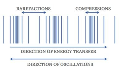
Waves transfer energy from one place to another without any net transfer of matter. These can be longitudinal or transverse:

<table border="1" id="bkmrk-longitudinal-maxima-" style="border-collapse: collapse; width: 100%;"><colgroup><col style="width: 16.7263%;"></col><col style="width: 83.3929%;"></col></colgroup><tbody><tr><td>Longitudinal</td><td>- Maxima at compressions and minima at rarefactions.
- Particles move parallel to the direction of energy travel.
- 

[![image.png](https://bookstack.asadhussain.net/uploads/images/gallery/2026-02/scaled-1680-/iOZimage.png)](https://scienceinfo.com/difference-between-transverse-and-longitudinal-wave/)
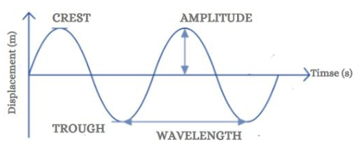
</td></tr><tr><td>Transverse</td><td>- Maxima at peaks and minima at troughs.
- Particles move perpendicular to the direction of energy travel.
- E.g. electromagnetic waves.

[![image.png](https://bookstack.asadhussain.net/uploads/images/gallery/2026-02/scaled-1680-/N3Pimage.png)](https://scienceinfo.com/difference-between-transverse-and-longitudinal-wave/)
</td></tr></tbody></table>

Waves that move away from a source are called progressive waves. However, this regards only the movement of **energy** - particles oscillate in place.

## Wave Terminology

<table border="1" id="bkmrk-displacement-the-dis" style="border-collapse: collapse; width: 100%;"><colgroup><col style="width: 50%;"></col><col style="width: 50%;"></col></colgroup><tbody><tr><td>Displacement</td><td>The distance traveled by a wave from its rest position.</td></tr><tr><td>Amplitude</td><td>The maximum displacement of oscillating particles in a wave.</td></tr><tr><td>Wavelength</td><td>The distance between two successive identical points of a wave.</td></tr><tr><td>Time period</td><td>The time taken for a wave to complete one pattern of oscillation.</td></tr><tr><td>Frequency</td><td>The number of oscillations at any point per unit time. Reciprocal of time period.</td></tr><tr><td>Phase difference</td><td>A measure of the difference in pattern of oscillation between two points of a wave. Measured in radians from 0 to 2pi.</td></tr><tr><td>Path difference</td><td>The difference between the distances traveled by two waves arriving at the same point. Usually measured in terms of wavelength, as path difference resets to 0m at a path difference equal to one wavelength.</td></tr></tbody></table>

## Oscilloscopes

An oscilloscope displays a voltage-time signal. It can be used to measure the output from a microphone or signal generator.

Each horizontal division represents a unit of time. The unit of time per division is determined with the time base - e.g. 0.002 s/div. This can help you determine time period.

Each vertical division represents a unit of voltage. The unit of voltage per division is determined with the sensitivity - e.g. 20 V/div (less sensitive) to 5 mV/div (far more sensitive). The more sensitive, the easier it is to determine the precise points where the wave crosses the axis, as the slope appears steeper and the peaks are more defined. However, it also increases the risk of the signal moving off-screen.

## Wave Equations

[![image.png](https://bookstack.asadhussain.net/uploads/images/gallery/2026-02/scaled-1680-/G7Fimage.png)](https://bookstack.asadhussain.net/uploads/images/gallery/2026-02/G7Fimage.png)

... where v is wave velocity, f is wave frequency, and lambda is wave wavelength. For EM waves in a vacuum, v = 3.00e8. For sound waves, v = 330.

[![image.png](https://bookstack.asadhussain.net/uploads/images/gallery/2026-02/scaled-1680-/N2Uimage.png)](https://bookstack.asadhussain.net/uploads/images/gallery/2026-02/N2Uimage.png)

... where I is the wave intensity (Wm<sup>-2</sup>), P is the wave power, and A is the surface area of the source (e.g. 4<span class="ZNx93QP1XNrBdT5MI6SY"><span class="expandableItem">π</span></span>r<sup>2</sup> for a sphere like the Sun).

Wave intensity is defined as the rate at which energy is transferred from one location to another as the wave travels through space. **It is proportional to the square of its amplitude** - e.g. if the amplitude decreases by a factor of 2, intensity reduces by a factor of **2<sup>2</sup> = 4**.

## EM Spectrum

Waves in the EM spectrum are transverse waves that can travel through a vacuum. They all have a magnetic and an electrical wave interlocked and at right angles to each other. In a vacuum, they travel at c = 2.98e8 ms<sup>-1</sup>.

<table border="1" id="bkmrk-wave-wavelength-%2F-m-" style="border-collapse: collapse; width: 51.4286%;"><colgroup><col style="width: 25.057%;"></col><col style="width: 33.6382%;"></col><col style="width: 41.5329%;"></col></colgroup><tbody><tr><td>**Wave**</td><td>**Wavelength / m**</td><td>**Frequency / Hz**</td></tr><tr><td>Radio</td><td>1e-1 to 1e4</td><td>3e4 to 3e9</td></tr><tr><td>Microwave</td><td>1e-4 to 1e-1</td><td>3e9 to 3e12</td></tr><tr><td><span style="background-color: rgb(191, 237, 210);">Infrared</span></td><td><span style="background-color: rgb(191, 237, 210);">7.4e-7 to 1e-3</span></td><td><span style="background-color: rgb(191, 237, 210);">3e11 to 4e14</span></td></tr><tr><td><span style="background-color: rgb(191, 237, 210);">Visible light</span></td><td><span style="background-color: rgb(191, 237, 210);">3.7e-7 to 7.4e-7</span></td><td><span style="background-color: rgb(191, 237, 210);">4e14 to 8e14</span></td></tr><tr><td><span style="background-color: rgb(191, 237, 210);">Ultra violet</span></td><td><span style="background-color: rgb(191, 237, 210);">1e-9 to 3.7e-7</span></td><td><span style="background-color: rgb(191, 237, 210);">8e14 to 3e17</span></td></tr><tr><td><span style="background-color: rgb(248, 202, 198);">X-Rays</span></td><td><span style="background-color: rgb(248, 202, 198);">1e-12 to 1e-7</span></td><td><span style="background-color: rgb(248, 202, 198);">3e15 to 3e20</span></td></tr><tr><td><span style="background-color: rgb(248, 202, 198);">Gamma rays</span></td><td><span style="background-color: rgb(248, 202, 198);">1e-16 to 1e-9</span></td><td><span style="background-color: rgb(248, 202, 198);">3e17 to 3e24</span></td></tr></tbody></table>

Ionising EM radiation has photons with sufficient energy to knock electrons from the shells of atoms.

99% of UV radiation is classified as UV-A, which is non-ionising. UV-B and UV-C are ionising, but UV-C is filtered out by the Earth's atmosphere, and the ionising nature of UV-B is mitigated using sunscreen creams.

## Properties of Waves

<table border="1" id="bkmrk-reflection-when-a-wa" style="border-collapse: collapse; width: 100%;"><colgroup><col style="width: 14.1072%;"></col><col style="width: 86.012%;"></col></colgroup><tbody><tr><td>Reflection</td><td>When a wave bounces off a surface.</td></tr><tr><td>Refraction</td><td>When a wave moves from one material into another of a different density, causing the wave to change speed and bend (unless traveling along the normal). Can be seen in glasses.</td></tr><tr><td>Diffraction</td><td>When a wave passes through an aperture that has a separation similar to the wave's wavelength, causing it to change direction.</td></tr><tr><td>Interference</td><td>When two or more waves overlap at a point, which has a particle displacement equal to the algebraic sum of all of the involved waves' displacements.</td></tr></tbody></table>

## Light Refraction

Refraction occurs when a wave moves from one material into another of a different density, causing the wave to change speed and bend (unless traveling along the normal).

Every material has a refractive index. The higher this index, the stronger the effect of refraction. The refractive index is given as:

[![image.png](https://bookstack.asadhussain.net/uploads/images/gallery/2026-02/scaled-1680-/LWwimage.png)](https://bookstack.asadhussain.net/uploads/images/gallery/2026-02/LWwimage.png)

... where v is the speed of the wave in the medium.

### Snell's Law

The refractive index also determines the angle at which a wave refracts, given by:

[![image.png](https://bookstack.asadhussain.net/uploads/images/gallery/2026-02/scaled-1680-/JZFimage.png)](https://bookstack.asadhussain.net/uploads/images/gallery/2026-02/JZFimage.png)

[![image.png](https://bookstack.asadhussain.net/uploads/images/gallery/2026-02/scaled-1680-/68Aimage.png)](https://bookstack.asadhussain.net/uploads/images/gallery/2026-02/68Aimage.png)

### Total internal reflection

This occurs when the angle of refraction (theta 2) is greater than or equal to 90 degrees. The incident angle causing a refracted angle of 90 degrees is known as the critical angle - any incident angle greater than this causes TIR. Take air and water for an example:

[![image.png](https://bookstack.asadhussain.net/uploads/images/gallery/2026-02/scaled-1680-/60Rimage.png)](https://bookstack.asadhussain.net/uploads/images/gallery/2026-02/60Rimage.png)

The critical angle is determined using:

[![image.png](https://bookstack.asadhussain.net/uploads/images/gallery/2026-02/scaled-1680-/53himage.png)](https://bookstack.asadhussain.net/uploads/images/gallery/2026-02/53himage.png)

## Polarisation

Serves as good evidence for the wave nature of light (on the particle nature, look at **4.5 - Quantum Physics**). All transverse waves can be polarised.

Light emitted from a source is unpolarised by default - the electric field of EM waves can be in any number of planes. Some crystalline materials can cause the oscillating fields to happen in only one plane. A wave with fields only one plane is known as plane polarised.

### Malus' Law

When a perfect polarising filter is put in front of a polarising wave with the vertical at an angle theta to the plane, the intensity of the output is:

[![image.png](https://bookstack.asadhussain.net/uploads/images/gallery/2026-02/scaled-1680-/Dqdimage.png)](https://bookstack.asadhussain.net/uploads/images/gallery/2026-02/Dqdimage.png)

## Interference and Superposition

The principle of superposition states that when two or more waves of the same type meet, the resultant wave can be found by adding the displacements of the individual waves.

[![image.png](https://bookstack.asadhussain.net/uploads/images/gallery/2026-02/scaled-1680-/OPkimage.png)](https://bookstack.asadhussain.net/uploads/images/gallery/2026-02/OPkimage.png)

Coherent waves have a constant frequency, and thus a constant phase difference.

With two waves in phase (path difference a multiple of lambda; phase difference 0 or a multiple of 2pi), total constructive interference occurs. This means the resultant wave has an increased amplitude.

With two waves out of phase (path difference an odd multiple of 1/2 lambda; phase difference an odd multiple of pi), total destructive interference occurs. This means the resultant wave has an amplitude of 0m.

In sound/spreading waves instead of waves in a linear path:

[![image.png](https://bookstack.asadhussain.net/uploads/images/gallery/2026-02/scaled-1680-/1qhimage.png)](https://bookstack.asadhussain.net/uploads/images/gallery/2026-02/1qhimage.png)

### Young's Double-Slit Experiment

Involves the emission of monochromatic light waves with wavelength lambda leaving a source and entering two slits with separation "a", causing diffraction. The diffracted waves travel a perpendicular distance "D" from the slits and superpose, constructively and destructively interfering to form fringes with separation "x" between maxima:

[![image.png](https://bookstack.asadhussain.net/uploads/images/gallery/2026-02/scaled-1680-/RoTimage.png)](https://bookstack.asadhussain.net/uploads/images/gallery/2026-02/RoTimage.png)

[![image.png](https://bookstack.asadhussain.net/uploads/images/gallery/2026-02/scaled-1680-/veWimage.png)](https://www.slideserve.com/tehya/young-s-double-slit-experiment)

[![image.png](https://bookstack.asadhussain.net/uploads/images/gallery/2026-02/scaled-1680-/eYGimage.png)](https://physics.stackexchange.com/questions/138625/double-slit-experiment-separation-between-fringes)

### Diffraction gratings

A diffraction grating is a piece of optical equipment made from glass, onto which hundreds/thousands of very thin, parallel, and equally spaced grooves have been accurately engraved. Measured in lines per mm. This greatly increases the resolution of interference patterns, which increases with number of slits. As you can see in the above image, a double slit pattern has much clearer fringe separations than the single slit pattern. Different orders of fringe are visible at path differences equal to multiples of lambda depending on slit separation, which define where fringes are visible - e.g.:

[![image.png](https://bookstack.asadhussain.net/uploads/images/gallery/2026-02/scaled-1680-/DHjimage.png)](https://bookstack.asadhussain.net/uploads/images/gallery/2026-02/DHjimage.png)

[![image.png](https://bookstack.asadhussain.net/uploads/images/gallery/2026-02/scaled-1680-/jZZimage.png)](https://bookstack.asadhussain.net/uploads/images/gallery/2026-02/jZZimage.png)

... where n is the order of the maximum (1, 2, 3), lambda is the wavelength of light, d is slit separation, and theta is the angle between the beam and the grating.

### Stationary Waves

Stationary waves are produced by interference in accordance with the principle of superposition. Two waves must be coherent, have roughly the same amplitude, and be traveling in opposite directions. Nodes are points of zero amplitude, where waves undergo destructive interference. Antinodes are points of maximum amplitude, where waves undergo constructive interference. Adjacent nodes and adjacent antinodes have a separation equal to half the wavelength.

#### Harmonics

Depending on the frequency of the stationary wave, it may have a different mode of harmonic:

[![image.png](https://bookstack.asadhussain.net/uploads/images/gallery/2026-02/scaled-1680-/ftqimage.png)](https://bookstack.asadhussain.net/uploads/images/gallery/2026-02/ftqimage.png)

#### Longitudinal Waves

In tubes, there is always a node at the closed end, and an antinode at an open end. This makes the fundamental and nth harmonics look different:

[![image.png](https://bookstack.asadhussain.net/uploads/images/gallery/2026-02/scaled-1680-/ERyimage.png)](https://bookstack.asadhussain.net/uploads/images/gallery/2026-02/ERyimage.png)

[![image.png](https://bookstack.asadhussain.net/uploads/images/gallery/2026-02/scaled-1680-/1xWimage.png)](https://bookstack.asadhussain.net/uploads/images/gallery/2026-02/1xWimage.png)

# 4.5 - Quantum Physics

## Photons

A quantum (plural: quanta) is a small discrete unit of energy.

A photon is a quantum of EM radiation.

Photon energies are always emitted in multiples of the Planck constant, h = 6.63e-34. Photon energy in joules is determined using:

[![image.png](https://bookstack.asadhussain.net/uploads/images/gallery/2026-02/scaled-1680-/KECimage.png)](https://bookstack.asadhussain.net/uploads/images/gallery/2026-02/KECimage.png)

These energies can also be expressed in electronvolts by dividing the energy in joules by e=1.6e-19. One electronvolt is defined as the kinetic energy gained by an electron when it is accelerated through a potential difference of 1V.

## The Photoelectric Effect

Each electron can only absorb one photon. This is known as the one-to-one relationship between electrons and photons.

Every metallic surface has a work function phi, which defines the minimum energy required for an electron to overcome electrostatic attraction between it and the metal cations, enabling it to be released/liberated from the metal surface. This energy can be obtained by absorbing a photon:

[![image.png](https://bookstack.asadhussain.net/uploads/images/gallery/2026-02/scaled-1680-/Adgimage.png)](https://bookstack.asadhussain.net/uploads/images/gallery/2026-02/Adgimage.png)

... where hf is the energy of the photon, phi is the work function, and KE<sub>max</sub> is the maximum additional energy from the photon transferred to the photoelectron's kinetic energy store. There is a maximum additional energy, as it is not the case that all photons from the same source have the same energy.

As light frequency is directly proportional to photon energy, the frequency of the EM radiation incident on a metal surface can affect whether or not electrons are liberated. This means a metal surface can also have a **threshold frequency**.

However, light intensity does **not** affect electron liberation - it only affects the number of photons released from the radiation source. For radiation above the threshold frequency, however, the rate of emission of photoelectrons is directly proportional to radiation intensity.

The photoelectric effect can be demonstrated using a gold leaf setup:

[![image.png](https://bookstack.asadhussain.net/uploads/images/gallery/2026-02/scaled-1680-/1qjimage.png)](https://bookstack.asadhussain.net/uploads/images/gallery/2026-02/1qjimage.png)

1. The electroscope is negatively charged, causing the brass stem and gold leaf to be negatively charged, repelling each other, causing the gold leaf to rise.
2. EM radiation above the threshold frequency is incident on the metal cap.
3. Electrons are liberated from the surface.
4. Electrons are transferred from the brass stem and gold leaf to the metal cap.
5. The reduction in strength of like negative charge reduces the electrostatic repulsion between the gold leaf and stem.
6. The gold leaf falls.

### Circuit setup

[![image.png](https://bookstack.asadhussain.net/uploads/images/gallery/2026-02/scaled-1680-/G2Gimage.png)](https://bookstack.asadhussain.net/uploads/images/gallery/2026-02/G2Gimage.png)

The stopping potential is the specific negative voltage applied to the collector plate that provides just enough electrical work to cancel out the maximum kinetic energy of the incoming photoelectrons, bringing them to rest exactly at the plate's surface. This can be determined by rearranging the following equation into the form y = mx + c:

[![image.png](https://bookstack.asadhussain.net/uploads/images/gallery/2026-02/scaled-1680-/f03image.png)](https://bookstack.asadhussain.net/uploads/images/gallery/2026-02/f03image.png)

<table border="1" id="bkmrk-%5Craggedright%7B-%5Ctext%7B" style="border-collapse: collapse; width: 100%;"><colgroup><col style="width: 99.881%;"></col></colgroup><tbody><tr><td>\\raggedright{

\\text{We know:}\\\\

  
KE\_{max} = eV\_s\\\\  
E = hf\\\\  
hf = \\phi + KE\_{max}\\\\

\\text{So:}\\\\

  
hf = \\phi + eV\_s\\\\  
V\_s = \\frac{h}{e}f - \\frac{\\phi}{e}

}

</td></tr></tbody></table>

Plotting a graph of stopping potential against radiation frequency can enable one to determine the value of h using the gradient multiplied by e = 1.6e-19.

## Wave-Particle Duality

This concept describes the idea that light, other types of EM radiation, and even matter could behave as both a wave and a stream of particles.

This can be observed by de Broglie's experiment involving the firing of electrons at a layer of graphite behind a screen. The result is concentric rings of alternating intensity:

[![image.png](https://bookstack.asadhussain.net/uploads/images/gallery/2026-02/scaled-1680-/FzCimage.png)](https://bookstack.asadhussain.net/uploads/images/gallery/2026-02/FzCimage.png)

This showed that electrons could diffract and interfere constructively and destructively. However, this was thought to be a behavior exclusive to waves.

The (de Broglie) wavelength of a particle can be determined with:

[![image.png](https://bookstack.asadhussain.net/uploads/images/gallery/2026-02/scaled-1680-/yGUimage.png)](https://bookstack.asadhussain.net/uploads/images/gallery/2026-02/yGUimage.png)

You can also substitute:

[![image.png](https://bookstack.asadhussain.net/uploads/images/gallery/2026-02/scaled-1680-/6Vnimage.png)](https://bookstack.asadhussain.net/uploads/images/gallery/2026-02/6Vnimage.png)

Wavelength is inversely proportional to mass. Since a wavelength similar to aperture size is required for diffraction, you wouldn't see a human diffracting walking through a door, for example. Assuming a mass 75kg and velocity 1ms<sup>-1</sup>:

[![image.png](https://bookstack.asadhussain.net/uploads/images/gallery/2026-02/scaled-1680-/GJLimage.png)](https://bookstack.asadhussain.net/uploads/images/gallery/2026-02/GJLimage.png)

... which is nowhere close to the width of any human's body, let alone the width of a doorway.